Cut and Trimming Functionalities
Different processes use the Trimming type functionalities to perform cuts and trims in the Engineering route. These functionalities are used according to the input and output Engineering components to be produced. The Cut and Trimming functionalities are:
1003 – Guillotine Cutter
1006 – Trilateral
1010 – Sheeter
1013 – Double Cutter (signatures)
1015 – Double Cutter (magazines)
1016 – Knife Die Cutting – Cut (angle bar)
1054 – Web Trimming
1080 – Inline Sheeter
1085 – Cutting (Association)
Note: Find this functionality's description at Using Components Association - .
1087 - Die Cutting
Note: Find this functionality's description at Creating Label Products - Setting functionality 1087 – Die cutting – Web.
Find bellow the detailed information of each functionality:
1003 – Guillotine Cutter
|
Use |
|
|
The 1003 – Guillotine Cutter functionality is used in the Engineering route for cutting sheet-type components and also in the following situations: Initial trimming; Cutting sizes in ½ sheet, ¼ sheet etc. (blank sheets); Cutting printed sheets; Final trimming; Separation of elements. |
|
|
Engineering Component Types Used |
|
|
Inputs |
Outputs |
|
1001 – Sheet |
1001 – Sheet |
|
Functionality Activation |
|
|
The Engineering activates the 1003 – Guillotine Cutter when it is necessary to to adjust the sheets sizes between processes. It can not be added by characteristics or Production Groups. |
|
|
Machines that Commonly Use the Functionality |
|
|
Cutting machines. |
|
|
Functionality Restriction |
|
|
It can not be related to other functionalities in the same Production Group. For more information, refer to "Relationships and Dependency Between unctionalities.” When the component has a handout type format, it can not be trimed before the folding functionality. The components having oher format types may not be trimmed in the processes previous to the folding functionality. The scope rules can only be applied if the 1003 – Guillotine Cutter functionality is classified as an alternative scope. For more information, refer to "Production Group Scopes.” |
|
|
Functionality’s Default Raw Material |
|
|
Does not have it. |
|
Linking this functionality to a Production Group
When adding this functionality to a production group, the system will display a window for you to configure the functionality further. Complete the fields in this window as described below:
|
Field |
Description |
|
Input Width |
Indicates if the restriction by machine’s feeder width is enabled. This option will be always selected for this functionality. |
|
Minimum |
Indicates the functionality will only be selected in Engineering for sheets wider than the minimum size set. The only restriction required for this functionality is the width restriction, because the sheet can be automatically rotated by Engineering in order to cut it. Therefore, all sides’ sizes will be considered as width. Allows entering the appropriate minimum width value. |
|
Maximum |
Indicates the functionality will only be selected in Engineering for sheets less wide than the maximum size set. The only restriction required for this functionality is the width restriction, because the sheet can be automatically rotated by Engineering in order to cut it. Therefore, all sides’ sizes will be considered as width. |
Click OK. When finished, click Save and Close.
1006 – Trilateral
|
Use |
|
|
The Engineering uses the 1006 – Trilateral functionality to trim finished products (perfect binded, saddle stiched, etc). It is possible to to trim the product’s top, bottom and front sides. |
|
|
Engineering Component Types Used |
|
|
Inputs |
Outputs |
|
1002 – Compound Component |
1002 – Compound Component |
|
Functionality Activation |
|
|
The 1006 - Trilateral functionality is activated every time the product has the following specification characteristics: Perfect Bind – Glued Perfect Bind Saddle Stitch – Wire Stitched Saddle Stitch – Glue in Line Loose Spine (Gathered only) Simplified Product Finishing The 1006 - Trilateral functionality may be activated, depending on the route, when the product has the following specification characteristics: Block Separated Block Wire-o Spine SpiralSpine For more information, refer to “Specification Characteristic Types” in iQuote User Guide – Product Specification Records. |
|
|
Machines that Commonly Use the Functionality |
|
|
Trilateral trimming machine. Finishing machines (perfect binding, saddle stitching etc) |
|
|
Functionality Restriction |
|
|
It is not applicable to handout, handout with templates and irregular format components. In these cases the engineering does not apply the trilateral margin on these components even if they are attached to the spine of a product that goes through a trilateral process. |
|
|
Functionality’s Default Raw Material |
|
|
Does not have it |
|
Linking this functionality to a Production Group
When adding this functionality to a production group, the system will display a window for you to configure the functionality further. Complete the fields in this window as described below:
|
Field |
Description |
||||||
|
Input Format |
Indicates if the minimum and maximum size for the input component will be restricted.
|
||||||
|
Thickness |
Indicates if the input component’s thickness will be restricted.
|
||||||
|
Bottom trilateral trimming |
Indicates if the component’s bottom trilateral margin value will be enabled. This option will be always enabled for the Trilateral functionality. This option should be kept selected for this functionality.
|
||||||
|
Face trilateral trimming |
Indicates if the component’s face trilateral margin value will be enabled. This option should be kept selected for this functionality.
|
||||||
|
Top trilateral trimming |
Indicates if the component’s top trilateral margin value will be enabled. This option should be kept selected for this functionality.
|
||||||
|
Cutter Simulation Mode |
In cases where the extra margins are greater than the maximum trimming, use this option to enforce a cutter process and cut off the extra margins. It enables you to choose between two simulations: "Maximum trimming margins used to validate the specification characteristic Trilateral Margins" uses the maximum trimming only to validate the specification characteristic (Trilateral margins). "Maximum trimming margins validates the layout size and triggers cutter when product margins are greater than the maximum value" simulates the cutter to cut off the extra margins in the layout before the fold. Otherwise, the system searches for another Trilateral that can do the cut. Note: The second option works only on stitched products that include a 1 up folded signature. |
||||||
|
Generic Characteristic |
Check this option when you want to trigger one of the following events when you select the Fanfold functionality in Jobs and Estimates: Create a new characteristic: it will add a new generic characteristic in the production group. Suppress a characteristic: the system will use the production group to suppress (i.e., complete) from the engineering process a generic characteristic that was part of the product specification. Note: for more information, refer to Generic Functionalities. |

Click Confirm. When finished, click Save and Close.
1010 – Sheeter
|
Use |
|
|
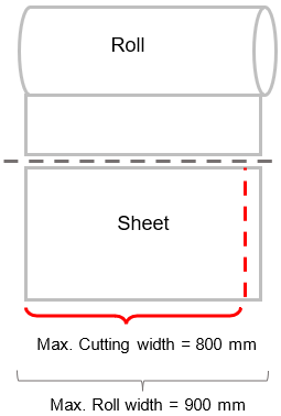
The Engineering uses the 1010 – Sheeter functionality for cutting paper roll into sheets. The cutting is made according to the image below:
|
|
|
Engineering Component Types Used |
|
|
Inputs |
Outputs |
|
1003 – Paper roll |
1001 – Sheet |
|
Functionality Activation |
|
|
The Engineering activates the 1010 – Sheeter functionality when it is necessary to transform a paper roll in paper sheets to be used, for example, in sheetfed presses. |
|
|
Machines that Commonly Use the Functionality |
|
|
Sheeters |
|
|
Functionality Restriction |
|
|
This process will always happen before the printing functionalities or element finishing functionalities. |
|
|
Functionality’s Default Raw Material |
|
|
Does not have it. |
|

Linking this functionality to a Production Group
When adding this functionality to a production group, the system will display a window for you to configure the functionality further. Complete the fields in this window as described below:
|
Field |
Description |
|
Height |
Indicates whether there will be height restrictions on the machine feeder. This option is always selected for the Sheeter functionality. |
|
Minimum |
Value to be considered as minimum cutting height restriction. If there is no cylinder height set, the Engineering simulates any cut size between the minimum and maximum. |
|
Maximum |
Value to be considered as a restriction of maximum cutting height. If there is no cylinder height set, the Engineering simulates any cut size between the minimum and maximum. |
|
Output Width |
Indicates whether there will be width restrictions on the machine feeder. This option is always selected for the Sheeter functionality. |
|
Minimum |
Minimum width of the input component. This functionality will not be selected in the Engineering if the paper rolls available are smaller than the minimum value defined. |
|
Maximum |
Maximum width of the input component. This functionality will not be selected in the Engineering if the paper rolls available are larger than the maximum value defined. |
|
Maximum number of rolls |
Indicates whether to allow inform the sheeter can cut more than one coil per entry. |
|
Quantity |
Number of coils that can cut sheeter on the same machine input. This field is displayed only if the maximum number of coils is enabled. |
|
Maximum number of columns in the layout |
Indicates the maximum number of elements in the sheet width/ roll. For example, if the value set is 2, the Engineering can only simulate one or two elements in the width direction of the sheet/ roll, as the following scheme:
Enable this option if you want to restrict the number of elements in the width direction of the sheet/ roll. |
|
Cylinder Height |
Indicates the cutting cylinder height. The cylinder height is the height of the sheet after cutting.
Enable this option if you want the cylinder height to be considered by Engineering as a sheet cutting height. |
|
Maximum not printed area on cylinder’s height |
Indicates whether there is a restriction for the maximum size of the area not printed remaining in relation to the cylinders. For example, when entering the value1 in this field, the remaining not printed area can not be greater than 1 mm. If so, the Engineering will not be calculated.
Enable this option only if the cylinder height option is also enabled. |
|
Paper effective use |
Indicates whether there will be a minimum % of paper use for the functionality. |
|
Percentage |
Minimum effective use percentage of paper so that this functionality can be selected. This field appears only if the Paper effective use option is enabled. For example, when the value set in this field is 50 %, the paper must have at least 50 % of effective use for this functionality to be selected. The use of paper is calculated using the following formula: Effective use = Product area in the layout / paper area Where: Paper area = Paper Width x Height Product Area in Layout = (total width of the product x Total height of product) x Number of elements in the layout For obtaining the total product’s width and height, it is necessary to sum up the flap margins, bleeding, spine and trilateral margins, if there are any. |
|
Allows trimming |
Indicates whether you can inform the measure value to trim the paper roll lateral. |
|
Maximum trimming |
Maximum value to be applied to the roll’s width. For example, if the cutting machine can trim 10 mm on each side of the roll, simply insert 20 mm in this field. This field will only be enabled if the Allows trimming option is enabled. |


Click Confirm. When finished, click Save and Close.
1013 – Double Cutter (signatures)
|
Use |
|
|
The Engineering uses the 1013 – Double Cutter (signatures) functionality for separating the components produced in double or triple layout and are separated before finishing, that is, before perfect biding, saddle stitching, gathering, etc. The following red line shows the cutting position. Double cut:
Triple cut:
To be possible to generate double layout components, these components must have the same characteristics, such as paper, color, format, etc. |
|
|
Engineering Component Types Used |
|
|
Inputs |
Outputs |
|
1001 – Sheet |
1001 – Sheet |
|
Functionality Activation |
|
|
The Engineering itself activates the 1013 – Double Cutter (signatures) functionality when there is the possibility of making a double layout, according to the size of components, machinery and raw materials. The double layout can also be manually selected in Engineering. For more information on how to make manual selections in Engineering, refer to "Route Selection in Engineering." |
|
|
Machines that Commonly Use the Functionality |
|
|
Cutting machines |
|
|
Functionality Restriction |
|
|
The Engineering can simulate a double layout with different components (handouts, signatures, etc.). However, this simulation option can not be manually selected. If the cost is the lowest, the Engineering selects the route, and it is not possible to simulate the separated products, except if a product has a different characteristic. If the cost is more expensive, the double layout with different components will not be available for manual selection. |
|
|
Functionality’s Default Raw Material |
|
|
Does not have it. |
|


Linking this functionality to a Production Group
When adding this functionality to a production group, the system will display a window for you to configure the functionality further. Complete the fields in this window as described below:
|
Field |
Description |
|
Width |
Indicates whether there will be a width restriction in the machine’s feeder. This option is always selected for functionality in 1013 – Double Cutter (signatures). This option should be maintained selected for this functionality. |
|
Minimum |
Minimum width for the input component. The Engineering may rotate the sheet to cut it, and in this case the sheet height will be considered as width, therefore this functionality has only a width restriction. |
|
Maximum |
Maximum width for the input component. The Engineering may rotate the sheet to cut it, and in this case the sheet height will be considered as width, therefore this functionality has only a width restriction. |
|
Cut Options |
Select this option to restrict the number of cuts or margins between cuts. If it is not selected, the Engineering can simulate the amount of cuts as needed without cutting margins. |
|
Cutting Margin Size |
Value to be applied as margin between components. For example: when entering 2 in this field, 2 margins of 1 mm will be applied on each side of the cut line, as the area in green:
If the trilateral cutting process is applied before the double cutting, it will be applied only to the bottom, top and front of the component. That is, the trilateral will not be applied to the double cutting are, as showed in the blue area in the image below:
If the trilateral cutting process is applied after the double cutting, it will be to the bottom, top and front of the component and it will be added to the double cutting margin.
|
|
Trimming maximum height |
Maximum height of each of the double component so that the cutting can be performed. |
|
Cutting Quantity |
Number of cuts the functionality may make. For example, when entering 1 in this field, the functionality will only make one cut, indicating the layout may be double.
When entering 2 in this field, the functionality may have up to 2 cuts, that is, the layouts may be double or triple.
This field is displayed only if the cutting options is enabled. |
|
Thickness |
Indicates whether there is a thickness restriction for the input component. |
|
Minimum |
Minimum thickness to be considered as a restriction for the components entering the functionality. If any component is less thick than the minimum, this functionality is not selected by the Engineering. This field appears only if the Thickness is enabled. |
|
Maximum |
Maximum thickness to be considered as a restriction for the components entering the functionality. If any component is thicker than the maximum, this functionality is not selected by the Engineering. This field appears only if the Thickness is enabled. |


Click Confirm. When finished, click Save and Close.
1015 – Double Cutter (magazine)
|
Use |
|
|
The Engineering uses the 1015 – Double Cutter (magazine) functionality for separating the components produced in double, triple layout etc and are separated after finishing, that is, after perfect biding, saddle stitching, gathering, etc. The following red line shows the cutting position. Double cut:
Triple cut:
The double cutting functionality is usually combined with additional functionalities, since the same machine can apply wire stitches and do the double cutting, for example. In this case, the Double-Cutter functionality should also be related to the functionality 1007 – Stitcher in the same Production Group. For more information on how to relate functionalities in the Production Group, refer to "Production Group Inputs.” |
|
|
Engineering Component Types Used |
|
|
Inputs |
Outputs |
|
1001 – Sheet (*) 1002 – Compound Component |
1001 – Sheet (*) 1002 – Compound Component |
|
Functionality Actuation |
|
|
The Engineering itself activates the 1015 – Double Cutter (magazines) functionality when there is the possibility of making a double layout, according to the size of components, machinery and raw materials. The double layout can also be manually selected in Engineering. For more information on how to make manual selections in Engineering, refer to "Route Selection in Engineering." |
|
|
Machines that Commonly Use the Functionality |
|
|
Finishing Machines (saddle stitching, perfect biding, etc) Cutting Machines |
|
|
Functionality Restriction |
|
|
It is possible that the Engineering simulates a double layout with different products. However, this simulation option can not be manually selected. If the cost is the lowest, the Engineering selects the route, and it is not possible to simulate the separated products, except if a product has a different characteristic. If the cost is more expensive, the double layout with different components will not be available for manual selection. |
|
|
Functionality’s Default Raw Material |
|
|
Does not have it. |
|


Note: The component 1001 – Sheet is used as input for functionality 1015 – Double Cutter (magazine) for cutting the pasted cover (coupling).
Linking this functionality to a Production Group
When adding this functionality to a production group, the system will display a window for you to configure the functionality further. Complete the fields in this window as described below:
|
Field |
Description |
|
Parallel trimming Rules |
Indicates the options are enabled to determine the number of the cuts and the double cutting margin. By default, this option is enabled for the Double Cutting (magazine) functionality. |
|
Input Format |
Indicates if the input component minimum and maximum height and width format will be restricted. |
|
Minimum (WxH) |
Minimum size for input. The width considered should be the same as the machine’s feeder. If there are no sheets available with the set minimum or maximum sizes and it is not possible to cut the machine to fit in the feeder, the functionality will not be selected by the Engineering. This field is displayed only if the Input Format option is enabled.
|
|
Maximum (WxH) |
Maximum size for input, where W is the machine’s feeder width. If there are no sheets available with the set minimum or maximum sizes and it is not possible to cut the machine to fit in the feeder, the functionality will not be selected by the Engineering. This field is displayed only if the Input Format option is enabled. |
|
Thickness |
Indicates whether there is a thickness restriction for the input component. |
|
Minimum |
Minimum thickness to be considered as a restriction for the components entering the functionality. If any component is less thick than the minimum, this functionality is not selected by the Engineering. This field appears only if the Thickness is enabled. |
|
Maximum |
Maximum thickness to be considered as a restriction for the components entering the functionality. If any component is thicker than the maximum, this functionality is not selected by the Engineering. This field appears only if the Thickness is enabled. |

Click Confirm. When finished, click Save and Close.
1016 – Cut (angle bar)
|
Use |
|
|
The Engineering uses the 1016 – Cut (angle bar) functionality for cutting the paper rolls that were not printed yet. The cutting is made in the vertical direction.
Before the paper roll is cut by the Cut (angle bar) functionality it will be necessary that the roll is cut horizontally first, transforming it into a sheet. Therefore, the 1010 – Sheeter functionality has to be used, which may or may not be in the same Production Group as the Cut (angle bar). |
|
|
Engineering Component Types Used |
|
|
Inputs |
Outputs |
|
1001 – Sheets |
1001 – Sheets |
|
Functionality Activation |
|
|
The Engineering itself activates the 1016 – Cut (angle bar) functionality when there are no recorded substrates within the minimum or maximum formats to be used by sheetfed machines. If there is a roll which can be cut on the width and height directions, the Engineering will try to cut it to produce the product. |
|
|
Machines that Commonly Use the Functionality |
|
|
Cutting machine |
|
|
Functionality Restriction |
|
|
This functionality accepts only cut sheets, which means the roll needs to pass through a sheeter process first to be subsequently cut by the Cut (angle bar) functionality. For this reason, the 1010 – Sheeter functionality must be enabled in at least one Production Group and may be in the same Production Group as the Cut (angle bar) functionality. For more information, refer to “Production Group Inputs.” |
|
|
Functionality’s Default Raw Material |
|
|
Does not have it. |
|

Linking this functionality to a Production Group
When adding this functionality to a production group, the system will display a window for you to configure the functionality further. Complete the fields in this window as described below:
|
Field |
Description |
||||
|
Output Width |
Indicates whether there will be a restriction for the minimum and maximum widths for the angular bar cutting. For example, if the maximum width 800, this will be the measure for cutting, and the paper roll may be larger than this value.
|
||||
|
Max Number of Slits |
Indicates whether this option will be enabled to enter the amount of cuts to be made in the roll’s height direction. This option is always enabled for the Cut (angle bar) functionality.
|

Click Confirm. When finished, click Save and Close.
1054 – Web trimming
|
Use |
|
|
The Engineering uses the 1054 – Web trimming functionality in two ways: To trim the paper roll when there is a left-over section of the paper (i.e., a waste) or when you printed the product on the roll more than once (e.g., side by side) and need to split it. This trimming is always made after the product has gone through the printer and the engineering can apply it on the sides or to divide the roll after the printing. The cut paper is discarded.
To divide the paper roll at the beginning of the process, before it goes through the printer, in order to avoid waste. You can use this when you have a large roll where you can print the product more than once so that, instead of throwing out the left-over paper, you can use it for the product.
Note: for the engineering to consider the second way of using the Web Trimming functionality, you need to configure it. Important: we made the second way of using the Web Trimming available on iQuote version 10.1. If your environment version is 10.0 or previous, you are able to use it as described on the first way only (i.e., after printing). |
|
|
Engineering Component Types Used |
|
|
Inputs |
Outputs |
|
1003 – Paper roll |
1003 – Paper roll |
|
Functionality Actuation |
|
|
The Engineering activates the 1054 – Web trimming functionality only when the recorded paper rolls are larger than the final product's size. The roll will be trimmed after or before going through the machines, depending on the case. |
|
|
Machines that Commonly Use the Functionality |
|
|
Cutting Machines. |
|
|
Functionality Restriction |
|
|
This functionality will not be selected if the component already has the functionality 1010 - Sheeter. |
|
|
Functionality’s Default Raw Material |
|
|
Substrates (represented by the input component 1003 – Paper roll). For more information, refer to "Substrate”. |
|


Linking this functionality to a Production Group
When adding this functionality to a production group, the system will display a window for you to configure the functionality further. Complete the fields in this window as described below:
|
Field |
Description |
|
Max Number of Slits |
You can use this field to define the maximum number of vertical cuts on the paper roll (other than the lateral trimming), in order to separate it in more than one roll. For example, if you define the Slits quanity as 2, the system will cut the label twice, as depicted in the image below with the dashed red line:
When this value is 0, the system only trims the paper roll and discards the waste. When the value is 1 or greater, the system cuts the roll more times, separating it in two or more rolls. |
|
Output Width |
Indicates if there is a restriction in the minimum and maximum width for the functionality’s output. This option is always enabled for functionality 1054 – Web trimming. Minimum: minimum width value for the functionality’s output. The system displays this field only if the Output Width option is enabled. Maximum: maximum width value for the functionality’s output. This field is displayed only if the Output Width option is enabled. |
|
Input Width |
Indicates if the minimum and maximum width for the functionality’s input will be restricted. This option is always enabled for functionality in 1054 – Web trimming. Minimum: minimum width value for the functionality’s input. The system displays this field only if the Input Width option is enabled. Maximum: maximum width value for the functionality’s input. This field is displayed only if the Input Width option is enabled. |

Click Confirm. When finished, click Save and Close.
1080 – Inline Sheeter
|
Use |
|
|
The Engineering uses the 1080 – Inline Sheeter functionality for cutting paper roll into sheets. The cutting is made according to the image below:
|
|
|
Engineering Component Types Used |
|
|
Inputs |
Outputs |
|
1003 – Paper roll |
1001 – Sheet |
|
Functionality Activation |
|
|
The Engineering activates the 1080 – Inline Sheeter functionality when it is necessary to transform a paper roll in paper sheets. |
|
|
Machines that Commonly Use the Functionality |
|
|
Sheeters |
|
|
Functionality Restriction |
|
|
Does not have it. |
|
|
Functionality’s Default Raw Material |
|
|
Does not have it. |
|

Linking this functionality to a Production Group
When adding this functionality to a production group, the system will display a window for you to configure the functionality further. Complete the fields in this window as described below:
|
Field |
Description |
|
Height |
Indicates whether there will be height restrictions on the machine feeder. This option is always selected for the Inline Sheeter functionality. |
|
Minimum |
Value to be considered as minimum cutting height restriction. If there is no cylinder height set, the Engineering simulates any cut size between the minimum and maximum. |
|
Maximum |
Value to be considered as a restriction of maximum cutting height. If there is no cylinder height set, the Engineering simulates any cut size between the minimum and maximum. |
|
Output Width |
Indicates whether there will be width restrictions on the machine feeder. This option is always selected for the Inline Sheeter functionality. |
|
Minimum |
Minimum width of the input component. This functionality will not be selected in the Engineering if the paper rolls available are smaller than the minimum value defined. |
|
Maximum |
Maximum width of the input component. This functionality will not be selected in the Engineering if the paper rolls available are larger than the maximum value defined. |
|
Maximum number of rolls |
Indicates whether to allow inform the sheeter can cut more than one coil per entry. |
|
Quantity |
Number of coils that can cut sheeter on the same machine input. This field is displayed only if the maximum number of coils is enabled. |
|
Maximum number of columns in the layout |
Indicates the maximum number of elements in the sheet width/ roll. For example, if the value set is 2, the Engineering can only simulate one or two elements in the width direction of the sheet/ roll, as the following scheme:
Enable this option if you want to restrict the number of elements in the width direction of the sheet/ roll. |
|
Cylinder Height |
Indicates the cutting cylinder height. The cylinder height is the height of the sheet after cutting.
Enable this option if you want the cylinder height to be considered by Engineering as a sheet cutting height. |
|
Maximum not printed area on cylinder’s height |
Indicates whether there is a restriction for the maximum size of the area not printed remaining in relation to the cylinders. For example, when entering the value1 in this field, the remaining not printed area can not be greater than 1 mm. If so, the Engineering will not be calculated.
Enable this option only if the cylinder height option is also enabled. |
|
Paper effective use |
Indicates whether there will be a minimum % of paper use for the functionality. |
|
Percentage |
Minimum effective use percentage of paper so that this functionality can be selected. This field appears only if the Paper effective use option is enabled. For example, when the value set in this field is 50 %, the paper must have at least 50 % of effective use for this functionality to be selected. The use of paper is calculated using the following formula: Effective use = Product area in the layout / paper area Where: Paper area = Paper Width x Height Product Area in Layout = (total width of the product x Total height of product) x Number of elements in the layout For obtaining the total product’s width and height, it is necessary to sum up the flap margins, bleeding, spine and trilateral margins, if there are any. |
|
Allows trimming |
Indicates whether you can inform the measure value to trim the paper roll lateral. |
|
Maximum trimming |
Maximum value to be applied to the roll’s width. For example, if the cutting machine can trim 10 mm on each side of the roll, simply insert 20 mm in this field. This field will only be enabled if the Allows trimming option is enabled. |


Click Confirm. When finished, click Save and Close.