Generic Functionalities
The Generic type functionalities are used when it is necessary to calculate some sort of process that does not have a specific functionality available within the system. The Generic functionalities may assume different roles, such as acting as an element finishing, a product finishing etc. These functionalities may also be used to replace functionalities that already exist, it should be avoided. It is recommended to always prioritize the use of specific functionalities to perform a particular process. The Generic functionalities are:
1 – Generic (Simple)
1042 – Generic (Layout)
Find bellow the detailed information of each functionality:
1 – Generic (Simple)
|
Use |
|
|
The Engineering uses the 1 – Generic (Simple) functionality for performing processes that do not have a specific functionality recorded. This functionality can be used if there are no restrictions of format, layout, margins, etc. This functionality can perform or create only one characteristic for other functionalities. |
|
|
Engineering Components Types Used |
|
|
Inputs |
Outputs |
|
All recorded Engineering components |
All recorded Engineering components |
|
Functionality Activation |
|
|
The functionality 1 - Generic (Simple) can be driven by the type of the following classes specification characteristic: Generic Characteristic with Notes field Generic Characteristic with Description field Generic Characteristic with List of field Generic Characteristic with List and Description fields Generic Characteristic with List and Value fields Generic Characteristic with Value field For more information, refer to this Specification Characteristic Type, see "Specification Characteristic Type – Generic Characteristic.” |
|
|
Machines that Commonly Use the Functionality |
|
|
Any machine that does not have a specific functionality Any handling that does not have a specific functionality |
|
|
Functionality Restriction |
|
|
This functionality can not be used when there is restriction of formats, layout, margins, etc. In this case, it should be used functionality in 1042 - Generic (Layout). For more information, refer to "Generic (Layout).” |
|
|
Functionality’s Default Raw Material |
|
|
This functionality does not have a default raw material. But it is possible to calculate the raw material in the Engineering using the customized raw material function. For more information on recording customized raw materials, refer to “Production Group Customized Raw Material.” |
|
Linking this functionality to a Production Group
When adding this functionality to a production group, the system will display a window for you to configure the functionality further. Complete the fields in this window as described below:
|
Field |
Description |
|
Characteristic |
Indicates if you want to enable the characteristic selection that this functionality can perform. You should keep this option enabled for this functionality. |
|
Suppress Characteristic |
When you enable the Create Engineering option in the Specification Characteristic Type record, the system creates a related Engineering Characteristic Type. In this Engineering Characteristic Type, you can choose whether it is going to be suppressed by a functionality or not. If it is going to be suppressed, you will need a machine for that. Therefore, you will need to look for and select this generic characteristic in the Suppress Characteristic field within the functionality setup in the Production Group. Note: if the Engineering Characteristic should not be suppressed, it will show up in the engineering, but the system will use it only as a filter. |
|
Create Characteristic |
When you enable the Create Engineering option in the Specification Characteristic Type record, the system creates a related Engineering Characteristic Type. In this Engineering Characteristic Type, you can choose whether it is going to be suppressed by a functionality or not. Considering that you chose to suppress a generic characteristic, you can select it in the Create Characteristic field within the functionality setup in the Production Group, so that the system adds the related Engineering Characteristic in the production group when this functionality is selected. Note: if the Engineering Characteristic should not be suppressed, it will show up in the engineering, but the system will use it only as a filter. |
Click Confirm. When finished, click Save and Close.
1042 – Generic (layout)
|
Use |
|
|
The Engineering uses the 1042 – Generic (layout) functionality for performing processes that do not have a specific functionality recorded. This functionality should be used if there are no restrictions of format, layout, margins, etc. |
|
|
Engineering Components Types Used |
|
|
Inputs |
Inputs |
|
1001 – Sheet 1002 – Compound component 1013 – Irregular sheet/ Carton 1014 – Component kitting 1022 – Sheet (handout) |
1001 – Sheet 1002 – Compound component 1013 – Irregular sheet/ Carton 1014 – Component kitting 1022 – Sheet (handout) |
|
Functionality Activation |
|
|
The functionality 1042 – Generic (layout) can be activated by the type of the following classes specification characteristic: Generic Characteristic with Notes field Generic Characteristic with Description field Generic Characteristic with List of field Generic Characteristic with List and Description fields Generic Characteristic with List and Value fields Generic Characteristic with Value field For more information, refer to "Specification Characteristic Type – Generic Characteristic” in iQuote User Guide – Product Specification Records. |
|
|
Machines that Commonly Use the Functionality |
|
|
Any machine that does not have a specific functionality Any handling that does not have a specific functionality |
|
|
Functionality Restriction |
|
|
This functionality should be used only when there are no specific functionalities that meet the product’s requirements. If too many Genric characteristics are created with the Layout simulation option enabled the Engineering calculation speed will be reduced. |
|
|
Functionality’s Default Raw Material |
|
|
This functionality does not have a default raw material. But it is possible to calculate the raw material in the Engineering using the customized raw material function. For more information on recording customized raw materials, refer to “Production Group Customized Raw Material.” |
|
Linking this functionality to a Production Group
When adding this functionality to a production group, the system will display a window for you to configure the functionality further. Complete the fields in this window as described below:
|
Field |
Description |
|||||||||||||||||
|
Characteristic |
Indicates if the option of selecting characteristics which can be performed by this functionality is enabled. This option should be kept enabled for this functionality. |
|||||||||||||||||
|
Suppress Characteristic |
When you enable the Create Engineering option in the Specification Characteristic Type record, the system creates a related Engineering Characteristic Type. In this Engineering Characteristic Type, you can choose whether it is going to be suppressed by a functionality or not. If it is going to be suppressed, you will need a machine for that. Therefore, you will need to look for and select this generic characteristic in the Suppress Characteristic field within the functionality setup in the Production Group. Note: if the Engineering Characteristic should not be suppressed, it will show up in the engineering, but the system will use it only as a filter. |
|||||||||||||||||
|
Create Characteristic |
When you enable the Create Engineering option in the Specification Characteristic Type record, the system creates a related Engineering Characteristic Type. In this Engineering Characteristic Type, you can choose whether it is going to be suppressed by a functionality or not. Considering that you chose to supress a generic characteristic, you can select it in the Create Characteristic field within the functionality setup in the Production Group, so that the system adds the related Engineering Characteristic in the production group when this functionality is selected. Note: if the Engineering Characteristic should not be supressed, it will show up in the engineering, but the system will use it only as a filter. |
|||||||||||||||||
|
Input Format |
Indicates if the minimum and maximum size for the input component will be restricted. |
|||||||||||||||||
|
Minimum (WxH) |
Input component’s minimum format in which the W value indicates the machine’s feeder width. If there are no sheets in this size or no sheet can be cut into this size, this functionality will not be considered by the Engineering. This field appears only if the Input format option is enabled.
|
|||||||||||||||||
|
Maximum (WxH) |
Input component’s maximum format in which the W value indicates the machine’s feeder width. If there are no sheets in this size or no sheet can be cut into this size, this functionality will not be considered by the Engineering. This field appears only if the Input format option is enabled. |
|||||||||||||||||
|
Margins
|
Indicates if margins will be added to the printing sheet. |
|||||||||||||||||
|
||||||||||||||||||
|
Layout Simulation |
Select this option should in order to the Engineering to make the printing imposition. By enabling this option, other layout simulation options are displayed. For printing functionalities, the layout simulation must be enabled. When this option enabled, the Engineering can simulate the cutting of the sheet before and after the 1042 – Generic layout functionality, using the 1003 – Guillotine Cutter functionality. The cutting position can be manually changed in the Engineering. For more information on manual editions in the Engineering, refer to "Route Selection in the Engineering.” |
|||||||||||||||||
|
Do not simulate work and turn |
Indicates if the Engineering should simulate work and turn printing or come and go with 2 grippers for this functionality. This field is displayed only if the Layout simulation is enabled. |
|||||||||||||||||
|
Simulate layout smaller than the minimum print size |
Indicates if the Engineering can simulate elements that are smaller than the machine’s minimum, due to: Any subsequent process that requires a specific format for the input component; It is not possible to add more elements in height or width directions so that the layout is larger than the minimum. For example, if a varnish machine requires the sheet is in a specific size, this size will be a limitation when organizing the elements in the sheet, and the final layout may be smaller than the minimum for the sheetfed printer.
If this option is enabled, it is possible to simulate the elements even if the layout is smaller than the machine’s minimum format. This field is displayed only if the Layout simulation is enabled. |
|||||||||||||||||
|
Grain |
Paper grain direction when entering the machine, which can be: All products in the same direction (width or height) Grain direction in width Grain direction in height Enables irregular grain direction This field is displayed only if the Layout simulation is enabled. |
|||||||||||||||||
|
Register Mark |
Available options for application of register marks, which can be: Controlled by functionality Always necessary Never necessary This field is displayed only if the Layout simulation is enabled. It is not used for printing functionalities, since those are the functionalities that generate register marks. |
|||||||||||||||||
|
Number of times the length size can be smaller than the width |
Maximum number of times that the height of the sheet may be smaller than width. This information will be used to optimize the simulations of possible layouts in the printer's input. By default, this field is filled with 4. This field is displayed only if the Layout simulation is enabled. |
|||||||||||||||||
|
Number of times the width size can be smaller than the length |
Maximum number of times that the sheet width may be smaller than height. This information will be used to optimize the simulations of possible layouts in the printer's input. By default, this field is filled with 1.2. This field is displayed only if the Layout simulation is enabled. |
|||||||||||||||||
|
Collecting Flap |
Indicates if the collation flap margin value is enabled. This option should be kept enabled for the collecting functionality. |
|||||||||||||||||
|
Value |
Margin value to be applied to the component’s collecting flap. The collecting flap position will be determined by the folding scheme. For more information, refer to "Folding Schemes.” This field is displayed only if the Collecting Flap option is enabled. |
|||||||||||||||||
|
Minimum |
Minimum margin value to be considered as component’s collecting flap. This value indicates the minimum margin to be applied to the flap, if the margin is manually edited in the Engineering. This field is displayed only if the Collecting Flap option is enabled. In order to make it possible to manually edit this value in engineering, leave this field blank or fill it with 0. |
|||||||||||||||||
|
Maximum |
Maximum margin value to be considered as component’s collecting flap. This value indicates the maximum margin to be applied to the flap if the margin is manually edited in the Engineering. This field is displayed only if the Collecting Flap option is enabled. In order to make it possible to manually edit this value in engineering, leave this field blank or fill it with 0. |
|||||||||||||||||
|
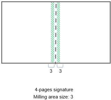
Milling area |
Indicates if the milling margin will be applied. This option should be kept enabled for this functionality. |
|||||||||||||||||
|
Size |
Size of the milling margin applied to the signature’s spine, as shown in the area marked in green. This field is displayed only if the Milling area options enabled.
|
|||||||||||||||||
|
Bottom trilateral trimming |
Indicates if the component’s bottom trilateral margin value will be enabled. This option will be always enabled for the Trilateral functionality. This option should be kept selected for this functionality. |
|||||||||||||||||
|
Value |
Trilateral margin value to be applied to the component’s bottom edge. This field appears only if the Bottom trilateral trimming option enabled. |
|||||||||||||||||
|
Minimum |
Minimum trilateral margin value considered for the component’s bottom edge if the margins are manually edited in the Engineering. This field is displayed only if the Bottom trilateral trimming option is enabled. If the entered value is 0 or if the field is left blank it will be possible to manually change this value in the Engineering. |
|||||||||||||||||
|
Maximum |
Maximum trilateral margin value considered for the component’s bottom edge if the margins are manually edited in the Engineering. This field is displayed only if the Bottom trilateral trimming option is enabled. |
|||||||||||||||||
|
Right trilateral trimming |
Indicates if the component’s frontal trilateral margin value will be enabled. This option should be kept selected for this functionality. |
|||||||||||||||||
|
Value |
Trilateral margin value to be applied to the component’s frontal edge. This field appears only if the Frontal trilateral trimming option enabled. |
|||||||||||||||||
|
Minimum |
Minimum trilateral margin value considered for the component’s front edge if the margins are manually edited in the Engineering. This field is displayed only if the Frontal trilateral trimming option is enabled. If the entered value is 0 or if the field is left blank it will be possible to manually change this value in the Engineering. |
|||||||||||||||||
|
Maximum |
Maximum trilateral margin value considered for the component’s frontal edge if the margins are manually edited in the Engineering. This field is displayed only if the Frontal trilateral trimming option is enabled. |
|||||||||||||||||
|
Top trilateral trimming |
Indicates if the component’s top trilateral margin value will be enabled. This option should be kept selected for this functionality. |
|||||||||||||||||
|
Value |
Trilateral margin value to be applied to the component’s top edge. This field appears only if the Top trilateral trimming option enabled. |
|||||||||||||||||
|
Minimum |
Minimum trilateral margin value considered for the component’s front edge if the margins is manually edited in the Engineering. This field is displayed only if the Top trilateral trimming option is enabled. If the entered value is 0 or if the field is left blank it will be possible to manually change this value in the Engineering. |
|||||||||||||||||
|
Maximum |
Maximum trilateral margin value considered for the component’s top edge if the margins is manually edited in the Engineering. This field is displayed only if the Top trilateral trimming option is enabled. |


Click Confirm. When finished, click Save and Close.